
Connecting a computer is perhaps the very first procedure that starts when setting up a computer at a new workstation. However, even here, there may be a bunch of questions about ‘where does everything go?’ And if you don’t have a connection guide, read our article to avoid getting confused with cables, ports, and connectors.
Connecting a computer is not complicated at all. It is designed in such a way that it is difficult to mix up the connectors, as it follows the principle of ‘foolproofing.’ The connectors have different shapes, colors, and numbers of pins. Depending on the type of case, the rear panel looks like this:
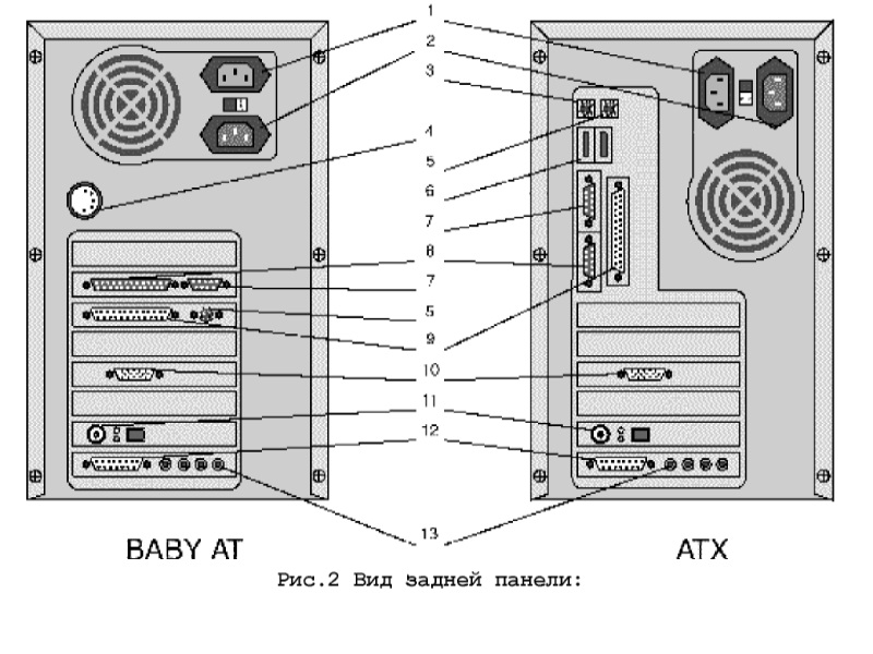
The list of connectors located on the rear panel of a computer includes:
1)Connector for connecting the monitor power cord (may be absent on ATX cases).
2)Connector for connecting the computer to an AC power source.
3)PS/2 connector for connecting a keyboard.
4)Connector for connecting a keyboard.
5)PS/2 connector for connecting a mouse.
6)USB ports.
7)Serial port (COM2).
8)Serial port (COM1).
9)Parallel port (LPT).
10)Video output (VGA/SVGA).
11)Connector for connecting to a local area network (depending on the computer model). This connector allows you to connect your computer to a local network.
12)MIDI/GAME port (depending on the computer model).
13)Ports for connecting external audio systems (depending on the computer model). Intended for connecting a microphone, speakers, and other audio equipment.
Serial ports (RS-232)
Through the 9-pin and 25-pin serial ports, you can connect a modem, mouse, and other devices that have a serial port. The mouse is typically connected to COM1.
Parallel port (LPT)
This connector allows you to connect a printer, scanner, or plotter that operates through a parallel port to your computer using a 25-pin bidirectional port with a “мother” connector.
VGA/SVGA Video Output
This connector is designed to connect a VGA/SVGA monitor to your computer using a 15-pin “мother” connector.
MIDI/GAME Port
This port allows you to connect a MIDI synthesizer or a game controller (joystick) to the computer. An additional adapter may be required to connect a MIDI synthesizer.
Connectors 1-10 are standard for all computer models. The presence of connectors 11-13 depends on the configuration. The placement of connectors is determined during assembly and can vary. Connecting the connectors should be done effortlessly and without the need for additional tools. The correct connection is ensured by using different types of connectors for each device. Secure all connectors with fasteners (if available).
P.S.: I tried to visually demonstrate and describe some straightforward tips. I hope at least something will be helpful to you. However, this is far from everything that can be thought of, so be bold and explore the website https://bip-mip.com/.