It is quite natural that both a beginner and an experienced amateur radio operator face the problem of lack of a power supply. In the most primitive case, this problem can be solved by using a circuit with a quenching capacitor. In our article we consider the use of a reactive resistor to obtain the desired voltage and give some tips on its calculation.
Power supply with quench capacitor:
There are many factors to consider when selecting a power supply circuit. Namely, the safety of the product, mass dimensions and design features, operating conditions, electrical characteristics, and much more.
First you need to look at: supply voltage; current draw; stability of your power supply, and signal ripple; power dissipation.
Power supply circuit with quench capacitor:
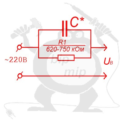
If for some reason you can’t use a transformer to step down the voltage, I recommend you adopt the quench capacitor circuit Figure 1

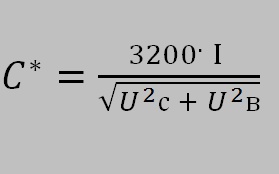
In this circuit, capacitor C* is a reactance that reduces the output voltage to the required level and is calculated by formula 1.

I — current consumption in A;
Uc — mains voltage (220 V);
UB — supply voltage of the device (output voltage);
If the output supply voltage you need is 10-20 volts or less, the capacitance of the quench capacitor can be determined using the simplified formula 2:

The nominal voltage (for which capacitor C* is designed) should be 2-3 times the mains voltage.
For example, for a 220 V mains supply, the rated voltage of capacitor C* must be at least 400 V.
The parallel resistance R1 is used to discharge the capacitor after disconnecting it from the mains. R1 must match the power consumption of your circuit (it must match the power dissipated by the load).
Such a circuit is useful for lowering the voltage, what you connect to its output is your will, the main thing is to observe the rules of electrical safety and competently select the elements of the projected circuit.

