
A beginner amateur radio operator simply cannot do without at least a simple power supply. When developing or customizing a device, a regulated power supply is an indispensable attribute. But if you are a beginner amateur radio enthusiast and can not afford an expensive tricked-out power supply, then this article will help you fill your need.
Power supply on LM317T chip, schematic:
There are innumerable schematics of various power supplies on the Internet. But even at first glance easy schemes, in the process of customization are not so easy. I recommend that you consider a very easy-to-set-up, cheap, and reliable power supply circuit on the chip stabilizer LM317T, which regulates the voltage from 1.3 to 30 V and provides a current of 1A (as a rule, this is enough for simple amateur circuits) Figure 1.

VD1 — VD4, VD6, VD7 — Semiconductor diodes type 1N5399 (1.5A 1000V) although you can use any other suitable for a maximum current of 1.5 amperes and voltage of about 50 volts. You can also use a diode bridge with the same characteristics. Who has what he has — he can use what he has:)
VD5 — An ordinary LED (it does not need to be soldered in), it signals the power on. Diode VD6 protects the circuit from current surges. VD7 — protects the chip from the parasitic discharge of capacitor C3.
R1 — about 18 Kohm (it is necessary to select it according to LED current).
R2 — It is not necessary to solder it in case you need to get non-standard voltage regulation limits. You just select it so that the sum of R2 + R3 = 5 Kohm.
R3 — 5.6 Com.
R4 — 240 Ohm.
C1 — 2200 µF (electrolytic)
C2 — 0.1 µF
C3 — 10 µF (electrolytic)
C4 — 1 µF (electrolytic)
DA1 — LM317T
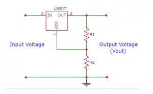
The main element in the circuit is LM317T microcircuit, you can easily see all its characteristics in the manual of the microcircuit. The only thing that should be separately noted is that it must be attached to the heatsink (Figure 2) so that the chip would not fail.

It has a maximum current of 1.5A according to the documentation — but I don’t recommend pushing it to such extreme operating modes.
I recommend using a transformer with a current reserve (3A current) so that in case of a sudden current surge it will not fail.
Every radio amateur makes printed circuit boards as he likes — but if you are too lazy to trace them — you can use my version of the printed circuit board Figure 3. You can open it with the program Sprint-Layout 5, or any other program in which you share it.
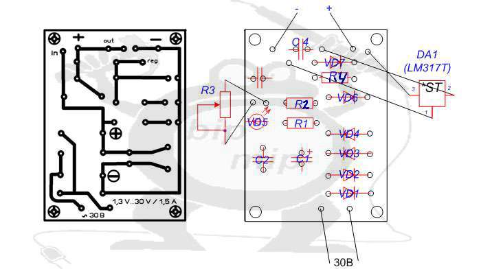
Before you start to make my variant of the board layout — once again review and analyze it!!! I traced the board under the photolithography method, so you can unfold it as you need. I tried to make the board the most universal for this circuit and made it for my needs. If you don’t solder resistor R2, you just need a jumper instead.
P.S.: I tried to clearly show and describe not tricky tips. I hope that at least something will be useful to you. But this is not all that can be invented, so go ahead, and study the site https://bip-mip.com/.

Additional recommendations for circuit customization:
For all resistors in the circuit it is better to put half-watt resistors, it is almost a guarantee of stable performance of the circuit, even in extreme operating conditions. Resistor R2 can be completely excluded from the circuit, I left a place for it for those cases when you need to get a non-standard voltage. Also, after a good digging on the Internet, I found a special calculator for recalculation of LM317, namely resistors in the voltage regulation control circuit.
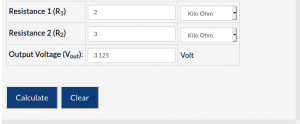
Resistors R3 and R4 are ordinary voltage dividers, so we can adjust them to the resistors we have on hand (within the specified limits) — this is very convenient and allows us to adjust the LM317T to any voltage without much difficulty (the upper limit can vary from 2 to 37V). For example, you can choose resistors so that your power supply is regulated from 1.2 to 20V — it all depends on the recalculation of the divider R3 and R4. You can find out the formula by which the calculator works by reading the datasheet for LM317T. Otherwise, if everything is assembled correctly, the power supply is immediately ready for operation.