
This article presents an elementary circuit of a capacitance meter on a logic chip. Such a classic and elementary circuit solution can be reproduced quickly and easily enough. Therefore, this article will be useful for a beginner amateur radio operator who wants to build an elementary capacitor capacitance meter.
Operation of a capacitance meter circuit:
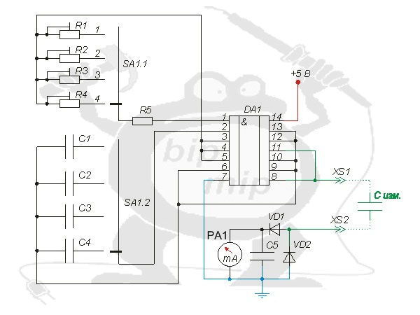
List of elements of the capacitance meter:
R1- R4 — 47 KОhm
R5 — 1,1 KOhm
C1 — 5 pF
C2 — 100 pF
C3 — 1500 pF
C4 — 12000 pF
C5 -0,1 µF
C is the capacitor whose capacitance you want to measure
SA1 — galette switch
DA1 — SN7400
VD1-VD2 — 1N903A
PA1 — Pointer indicator head (full deflection current 1 mA, frame resistance 240 Ohm)
XS1- XS2 — alligator connectors
This version of capacitor capacity meter has four ranges, which can be selected by switch SA1. For example, in position “1” you can measure capacitors with a capacitance of 50 pF, in position “2” — up to 500 pF, in position “3” — up to 5000 pF, in position “4” — up to 0.05 µF.
The elements of the DA1 chip provide sufficient current to charge the measured capacitor (C ism.). It is especially important for the measurement accuracy to adequately select diodes VD1-VD2, they should have the same (most similar) characteristics.
Setting up the circuit of the capacitance meter:
To set up such a circuit is quite simple, you need to connect a C-meter with known characteristics (with known capacitance). Select the necessary measuring range with the switch SA1 and rotate the knob of the build-up resistor until you reach the desired reading on the indicator head PA1 (I recommend that it be calibrated in accordance with your readings, this can be done by disassembling the indicator head and gluing a new scale with new inscriptions).